changing shapes
Rotating shape
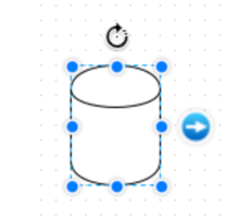
When creating a new shape, it always starts in a direction relative to the page. For example, when creating a cylinder, it always appears like this:

It is possible to rotate any shape, and there are several ways to do this. In order to use any of them, we must first click on the shape to highlight it.

Notice the curved arrow above the shape.
Clicking the arrow once rotates the object 90 degrees clockwise. Therefore, in order to rotate the cylinder 270 degrees so that the top points to the left, we only need to click the arrow three times.

We are not limited to multiples of 90 degrees.
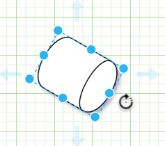
By clicking and holding down the mouse, then rotating the cursor left or right, we can rotate the shape counterclockwise or clockwise, respectively. Next we see a cylinder rotating 120 degrees counterclockwise.

Change Size
When creating a new shape, it always starts to display at the same size. For example, ellipses are always created like this:

You can adjust the size of any shape. There are several ways to do this.
In order to use any of them, we must first click on the shape to highlight it.
Notice the blue dots around the highlighted frame. We can resize the shape by clicking and dragging one of the points.
Sometimes we want to keep the aspect ratio of the shape (i.e. keep the same aspect ratio).
To do this, click and drag one of the corners.

Above we have enlarged the shape; It is the same as the original shape, but enlarged.
On the contrary, we can only change the height or width. We do this by dragging a point on a horizontal line (height adjustment) or a vertical line (width adjustment).

Above we only adjusted the height of the ellipse. Now the ellipse looks more like a circle.
Use connector
In fact, there are two ways to connect connectors to shapes.
Let’s look at them now. We can create anchor connection or floating connection. Anchor connector Suppose we want to connect two rectangles.

Connect two shapes by finding a connection point on the first shape, and then click and drag until a connection point is found on the second shape.

Release the connection here.
We have now created an anchor connection point.
This means that as the shape moves, the connector will always be connected to the same connection point.
In our example, both ends of the connector are anchored.

One of the best ways to show how this works is to rotate one of the shapes several times.

You can see that the connector follows the connection point. If we rotate the first shape, we will see the same thing.
Floating connector
Let’s look at another way to connect the two rectangles.

We will find a connection point on the first shape and click and drag as before. But this time, we will drag the connector to the center of the second shape so that the whole shape is outlined with a solid blue line.
Release the connection here. We have now created a floating connection point. This means that as the shape moves, the connector adjusts the connection point of its connection. Please note that it looks the same as the anchor connection point.

However, if we rotate the second shape, we will see a difference.

There are many ways to establish a connection between two points. In this section, we have been studying how to create connections to existing shapes. There are also some ways to create a new shape and create a connection to it.
One is to use an arrow symbol to the right of the highlighted shape.
Another method is to create a new connection with the copy on connection option enabled so that the new connector terminates in a copy of the original shape.
Anchor
It is possible to arrange connections in different ways. This is usually useful in more complex charts where connecting lines between different shapes may need to avoid any intermediate shapes. In addition, the orthogonal connector we are currently using may not be the most suitable choice. We have seen some layouts/arrangements using curved connectors in the insertion function.
You can merge various types of connector shapes by using waypoints.
Let’s start with a simple diagram: two rectangles connected by a connector. The starting point of the connector is fixed on the first rectangle. The end of the connector has a floating connection to the second rectangle. Let’s click on the connector to highlight it.

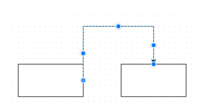
You can see a blue dot in the middle of the connector. This is a waypoint. We can use it to change the path of the connector. Click and drag the blue dot up.

We have changed the path of the connector. Please note that both ends of the connector are anchored and the other floating as we expect. When we create a new part of the connector, more waypoints will appear to allow us to further manipulate the path.
Let’s select a new waypoint, the waypoint above the first rectangle, and drag it slightly to the right.

Now let’s go to the toolbar and select the path point drop-down menu. There are different types of connectors. We are currently using orthogonal connectors, which can bend, but only at right angles.

Click the first menu option straight line (represented by a straight line connector) to make the connector straight.
We have returned the connector to its original path.
But now, even if the connector is highlighted, there is no central waypoint. Straight connectors cannot deviate from straight lines, so no connectors are required.
If we move the second rectangle by dragging it, the connector will move with it-but it cannot deviate from the straight line.
You may not have seen this before.
As you expected, the floating connection to the second rectangle has moved, but it is no longer connected to any connection point on the second rectangle. Compare this with the default orthogonal connector, which moves only north, east, south or west, so even floating connections point to connection points at the edges of the rectangle.

Now the connector is curved and new path points appear, allowing us to customize the path. We can click and drag a waypoint, just as we did in the orthogonal example.


We have a new connector path and we have added new path points. Finally, several options in the right-click menu may be useful. After selecting the connector, adjust the drawing.

There are several waypoint-related options to choose from. Click Clear waypoints, which will delete the waypoints we added manually. Path changes associated with these waypoints are also deleted. In fact, we have already returned to before we changed the road.
We can also remove additional waypoints individually by right-clicking one of the waypoints and selecting Remove waypoint.