what is Network topology diagram
The network topology diagram refers to the physical layout of various machines and equipment interconnected by transmission media, i.e. which method is used to interconnect the electronic computers and other machines and equipment in the internet. The topology draws the Internet configuration and the connection between cloud servers and service centers. There are many kinds of topological structures of the Internet, including star structure, ring structure and bus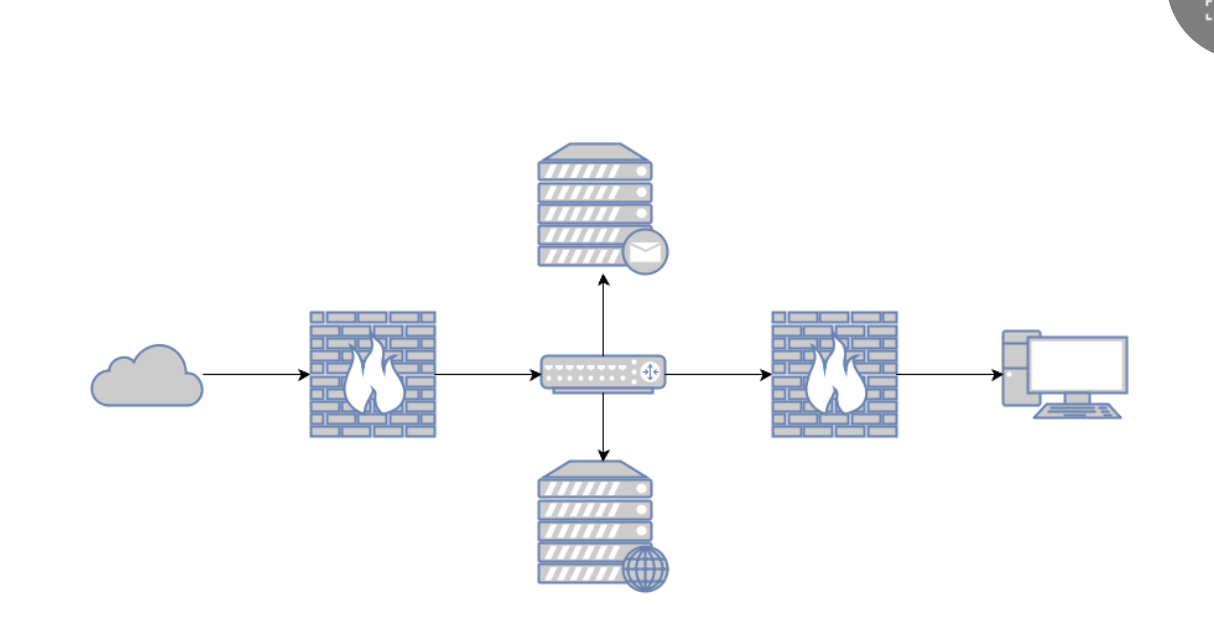
Advantages and Disadvantages of Network topology diagram
Network topology diagram is often drawn by Network topology diagram software. Network topology diagram software allows users to easily add, modify, save and copy Network topology diagram. If these things are done by hand, it will be a lot of trouble. However, it is not a problem for Network topology diagram software. In addition, for users who have access to the Internet, Network topology diagram in the form of software can undoubtedly be more easily shared with others.
Network topology diagram Category
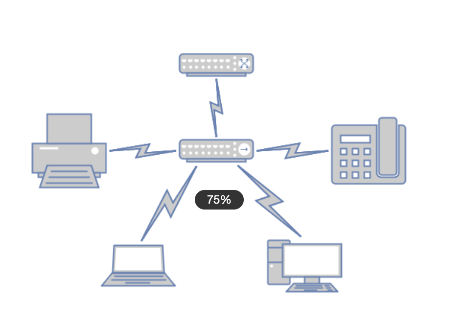
Star topology
The star structure is the oldest type of connection, and the telephone that everyone uses every day belongs to this structure. Star structure refers to the connection of workstations into a network in a star-like manner. The network has a central node, and other nodes (workstations, servers) are directly connected to the central node. This structure takes the central node as the center, so it is also called a centralized network.
This structure facilitates centralized control because communication between end users must pass through a central station. Due to this feature, it also brings the advantages of easy maintenance and safety.
When the end user equipment is shut down due to failure, the communication between other end users will not be affected.
At the same time, its network delay time is small and its transmission error is low.
However, the disadvantage of this structure is that the central system must have extremely high reliability, because once the central system is damaged, the whole system tends to collapse.
For this central system, dual-computer hot backup is usually adopted to improve the reliability of the system.
Ring network topology
Ring structure is widely used in LAN. The transmission medium in this structure goes from one end user to another until all end users are connected into a ring. Data is transmitted between nodes along one direction in the loop, and information is transmitted from one node to another. This structure obviously eliminates the dependence of end users on the central system when communicating.
The loop structure is characterized in that each end user is connected to two neighboring end users, thus there is a point-to-point link, but it always operates in a one-way manner, thus it is called upstream end user and downstream end user. Information flows along a fixed direction in the network. Two nodes have only one road, thus simplifying the control of path selection.
Each node on the loop is bootstrapping control, so the control software is simple. Since the information source passes through each node in series in the loop, when there are too many nodes in the loop, the information transmission rate will be affected and the response time of the network will be prolonged. The loop is closed and not easy to expand. Low reliability, a node failure, will cause paralysis of the entire network; It is difficult to maintain and locate the branch node faults.
Bus topology
Bus structure is a way to connect all end users with the same media or cable, that is to say, the physical media of the connected end users are shared by all devices, all workstations are equal in status, there is no central node control, the information on the public bus is mostly transmitted serially in baseband form, and its transmission direction always spreads from the node sending the information to both ends, just like the information transmitted by the broadcasting station, so it is also called broadcast computer network. Each node checks its address when receiving information to see if it matches its workstation address.
If it matches, it receives information on the Internet. One of the problems that must be solved when using this structure is to ensure that end users cannot have conflicts when using media to send data. This is quite simple when configuring point-to-point links. If this link is half-duplex operation, only a very simple mechanism is needed to ensure that the two end users work alternately. In the one-point to multi-point mode, access to the line is determined by inquiry from the control terminal. However, in LAN environment, because all data stations are equal, the above mechanism cannot be adopted. Therefore, a media access method used in bus sharing network is studied: carrier sense multiple access with collision detection, abbreviated as CSMA/CD. This structure has the advantages of low cost, flexible access of data end users, and failure of a site or one end user does not affect communication of other sites or end users. The disadvantage is that only one end-user can send data at a time, and other end-users must wait to obtain the sending right. The media access acquisition mechanism is more complex; Maintenance and branch node fault finding are difficult. Despite the above shortcomings, it is the most commonly used LAN technology due to simple wiring requirements, easy expansion, end user failure, addition and deletion does not affect the work of the whole network.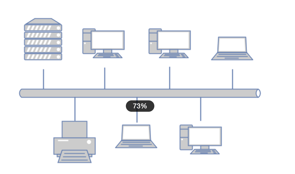
Distributed topology
A distributed network is a form of network in which computers distributed in different places are interconnected by lines.
The network with distributed structure has the following characteristics: due to the adoption of decentralized control, even if a local fault occurs in the whole network, the operation of the whole network will not be affected, thus having high reliability;
The shortest path algorithm is adopted in the network, so the network delay time is less, the transmission rate is high, but the control is complicated. Data links can be directly established between each node, with the shortest information flow. It is convenient to share resources throughout the network.
Disadvantages are long cables for connecting lines and high cost.
Complex network management software; Packet switching, path selection and flow direction control are complicated. This structure is not adopted in general local area networks
Tree topology
The tree structure is a hierarchical centralized control network. Compared with the star type, its communication lines are shorter in total length, lower in cost, easy to expand nodes, and easier to find paths. However, except for leaf nodes and their connected lines, any node or its connected line faults will affect the system.
Mesh topology
In a mesh topology, each device in the network has a point-to-point link connection, which is uneconomical. This method is only used when each station sends information frequently. Its installation is also complicated, but the system has high reliability and fault tolerance. Sometimes referred to as a distributed structure.
Cellular topology
Cellular topology is a common structure in WLAN. It is characterized by point-to-point and multi-point transmission of wireless transmission media (microwave, satellite, infrared, etc.), and is a wireless network suitable for city network, campus network and enterprise network.
Hybrid topology
Hybrid topology is a network structure that combines star-shaped structure or ring-shaped structure with bus-shaped structure. Such topology structure can better meet the expansion of larger networks, solve the limitation of star-shaped network in transmission distance, and at the same time solve the limitation of bus-shaped network in the number of connected users. Advantages of hybrid topology: It is widely used. It solves the shortage of star and bus topology and meets the actual needs of large companies in networking. The expansion is quite flexible. Faster speed: because its backbone network uses high-speed coaxial cables or optical cables, the entire network should not be subject to too many restrictions on speed. The disadvantage is that the bus length and the number of nodes are also limited because broadcast message transmission is still adopted. The weakness that the network speed with the same bus network structure will decrease with the increase of users. It is difficult to maintain, which is mainly restricted by the bus network topology. If the bus is broken, the entire network will be paralyzed.
Use online tools to make example renderings.
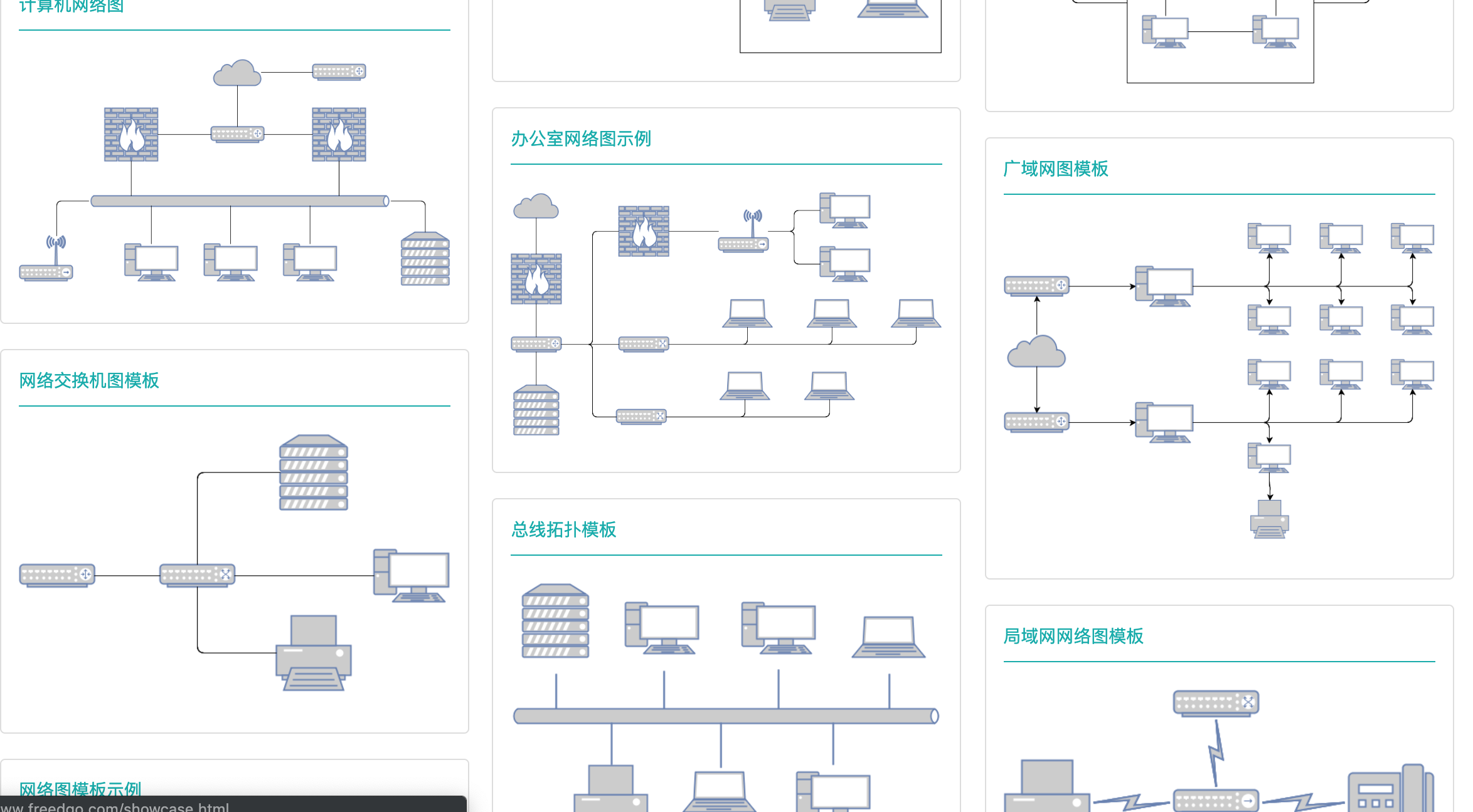
Network topology diagram
There are many ways to create Network topology diagram.
if you choose to draw Network topology diagram online, it is recommended to use the Online Drawing website: freedgodesign.
Freedgo Design, whose access address is: https://www.freedgo.com. Freedgo design Online Drawing website is a multi-type graphic design software.
The content of the software comes with rich geometric graphics templates, which can be used to draw professional Network Topology Diagrams, swimlane diagrams, impact diagrams, SDL diagrams, approval diagrams, accounting Network Topology Diagrams, etc. It provides rich examples of network diagrams and is easier to use.
step1:
visitor https://www.freedgo.com ,First register a user, and after successful registration, log in to Home
step2:
visitor https://www.freedgo.com/draw-index.html ,Enter the “drawing page” or click “start making” from the menu at the top of the “home page” page.。
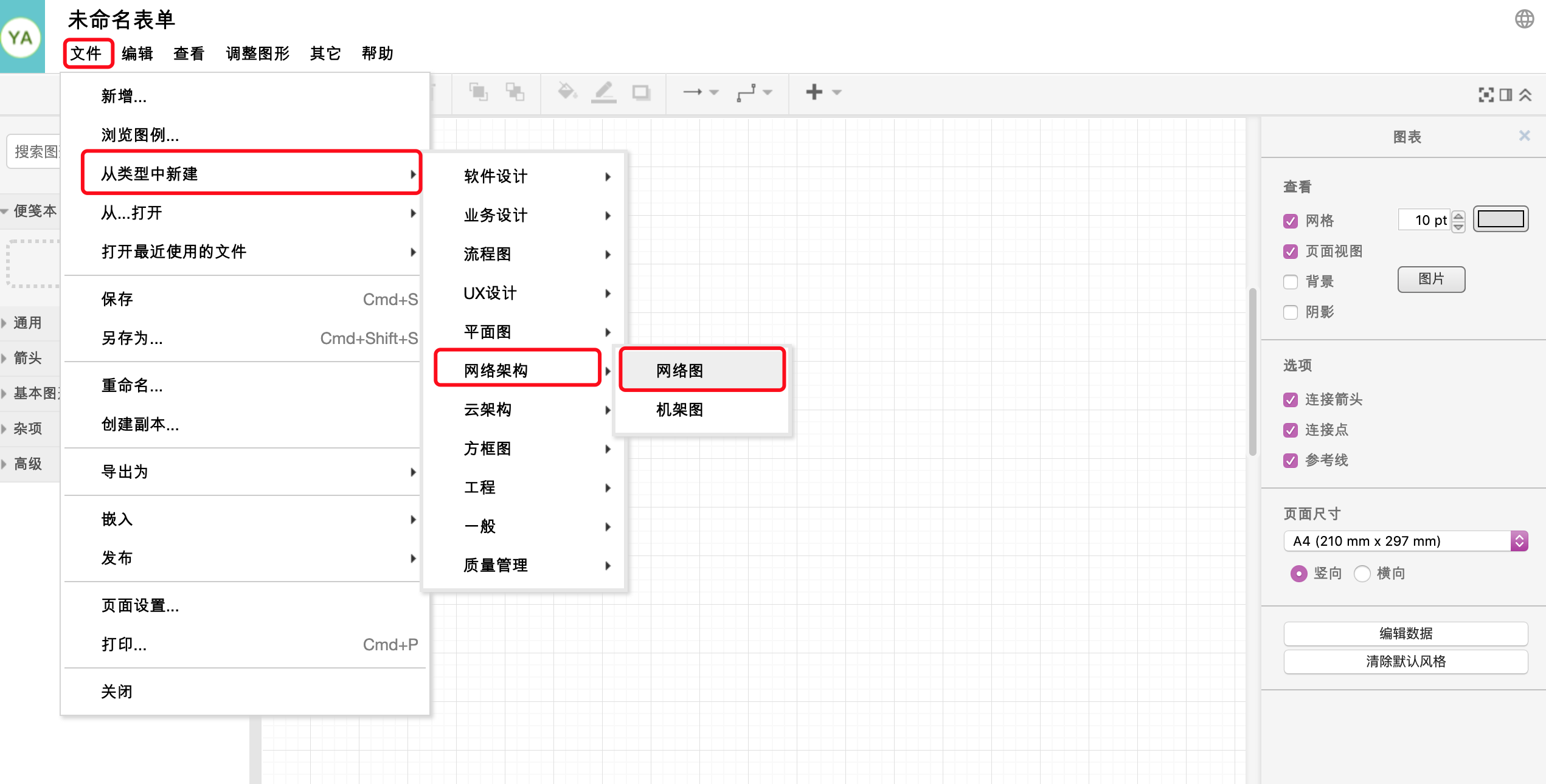
After entering the drawing page, click file-> new from type-> network architecture-> network diagram.
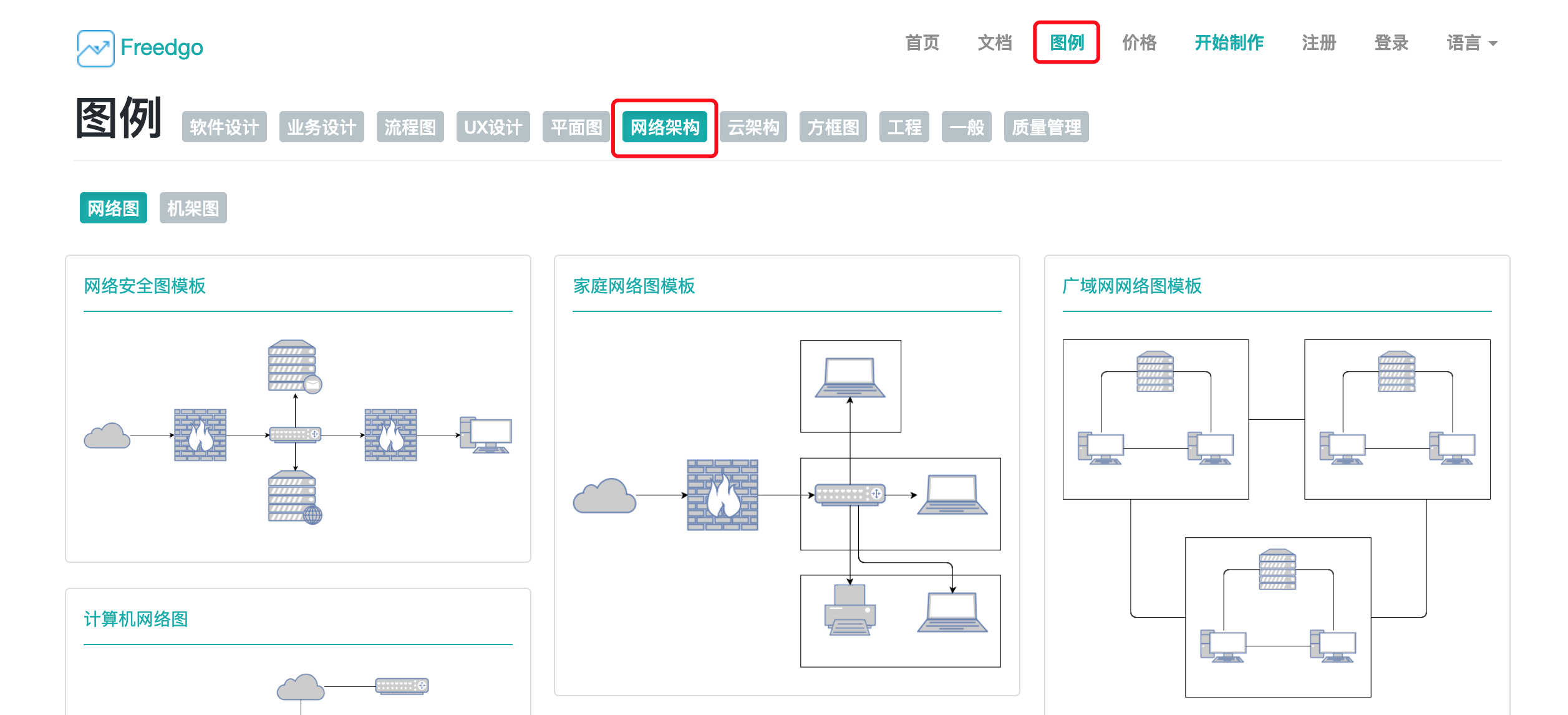
Or click on the legend, find the “network architecture”-> “network diagram” in the legend, and select a similar legend to change it.
step3:
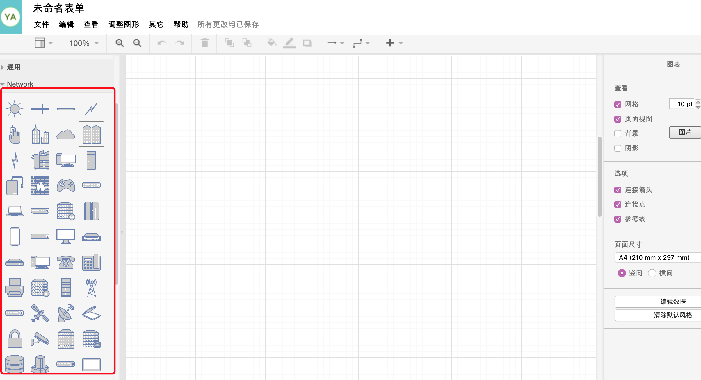
Drag the appropriate geometric figure from the symbol bar on the left to the canvas. After releasing, the oval figure will be fixed on the canvas. Double-click the geometric figure and enter text. When the mouse is placed on the graph, A “small triangle” will be displayed around the graph to facilitate users to quickly generate new graphs after clicking.
step4:
The software provides a variety of connection styles. In this Network topology diagram, you can choose a common right-angle connection line. On the connection line, you can also enter text for further explanation.

step5:
The Network topology diagram production tool has a set of rich styles. Users can fill closed graphics with monochrome, gradient and text size, position and color adjustment. The color value of the patterned Network topology diagram has improved a lot.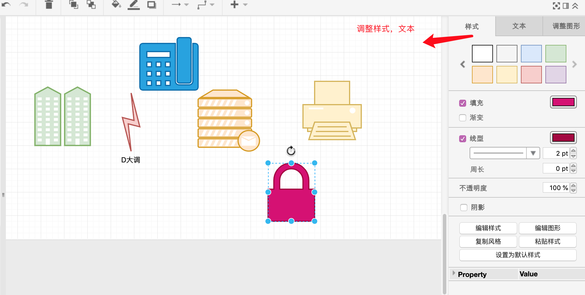
step6:
According to the drawing requirements, the Network topology diagram is drawn step by step. Finally, the whole painting task was completed.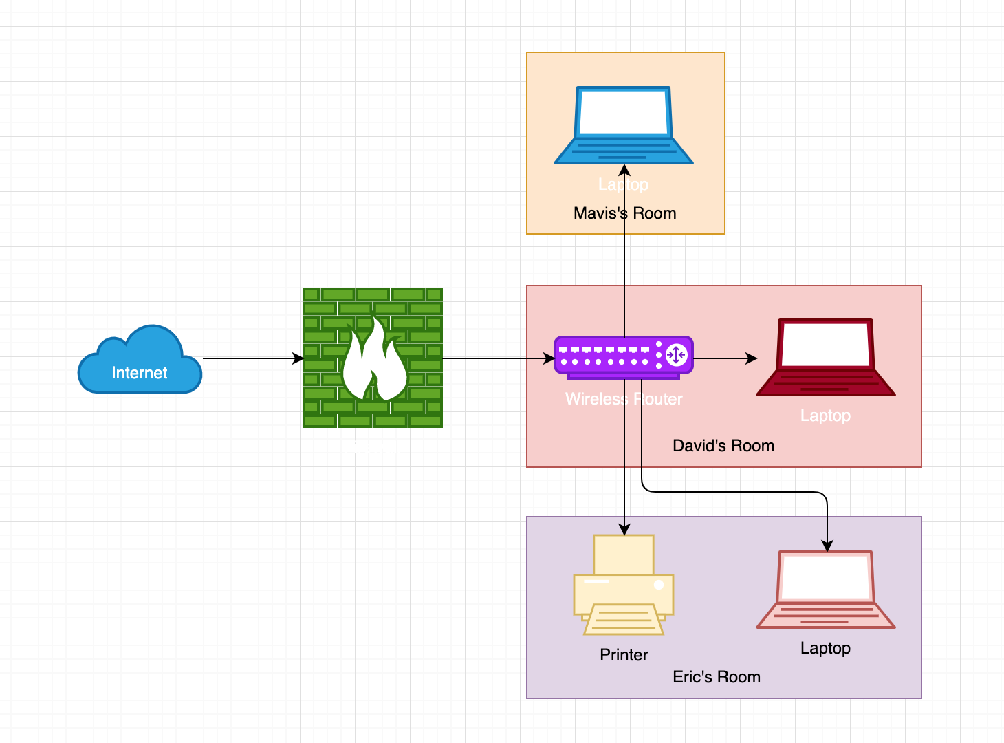
For more examples of basic processes, please refer to example Or direct access : https://www.freedgo.com/showcase/network_diagram/NetworkDiagram-1.html